25th ICPC
ICPC 2001
Vancouver, Canada · 9 problems
- 1St. Petersburg State University · SPBSU#1Andrei Lopatine, Nikolai Durov, Victor Petrov6
- 3St. Petersburg Institute of Fine Mechanics & Optics · SPbIFMO1Andrey Stankevich, Denis Kouznetsov, Georgiy Korneev6
- 6University of Warsaw · EaglesAndrzej Gasienica-Samek, Marcin Stefaniak, Tomasz Czajka5
Problems
9 problemsProblem A · Airport Configuration Input: airport.in
ACM Airlines is a regional airline with von Neumann Airport as its home port. For many passengers, von Neumann Airport is not the start of their trip, nor their final destination, so many transfer passengers pass through the airport.
The von Neumann Airport has a corridor layout. Arrival gates are located, equally spaced, at the north side of the corridor. Departure gates are at the south side of the corridor, equally spaced as well. The distance between two adjacent gates equals the width of the corridor. Each arrival gate is assigned to exactly one city, and the same holds for the departure gates. Passengers arrive at the arrival gate assigned to their city of origin and exit the terminal or proceed to a connecting flight at a gate assigned to their destination city. For this problem, only passengers with connecting flights are considered.
Transferring passengers generate a lot of traffic in the corridor. The average number of people traveling between cities is known beforehand. Using this information, it should be possible to reduce the traffic. If transfers from city Cx to city Cy occur very frequently, it may help to locate the gates assigned to these cities near or even directly opposite each other.
Due to the presence of shops and gardens it is not possible to cross the corridor diagonally, so the distance between arriving gate G1 and departing gate G3 (see diagram) equals 1 + 2 = 3.
You must assess total traffic load for several different configurations. The traffic load between an origin and destination gate is defined as the number of origin to destination passengers multiplied by the distance between the arriving and departing gate. The total traffic load is the sum of the traffic loads for all origin-destination pairs.
Input
The input file contains several test cases. The last test case in the input file is followed by a line containing the number 0.
Each test case has two parts: first the traffic data, then the configuration section. 1 G1 C2 G2 C3 G3 C1 C1 G1 C2 G2 C3 G3
1 Arrival Gates
Departure Gates shop garden The traffic data starts with an integer N (1 < N < 25), representing the number of cities. The following N lines each represent traffic data for one city. Each line with traffic data begins with an integer in the range 1..N identifying the city of origin. This is followed by k pairs of integers, one pair for every destination city. Each pair identifies the destination city and the number of passengers (at most 500) traveling from the city of origin to this destination city.
The configuration section consists of one or more (at most 20) configurations and ends with a line containing the number 0.
A configuration consists of 3 lines. The first line contains a positive number identifying the configuration. The next line contains a permutation of the cities, as they are assigned to the arrival gates: the first number represents the city assigned to the first gate, and so on. The next line in the same way represents the cities as they are assigned to the departure gates.
Output
For each test case, the output contains a table presenting the configuration numbers and total traffic load, in ascending order of traffic load. If two configurations have the same traffic load, the one with the lowest configuration number should go first. Follow the output format shown in the sample below.
Sample Input
3
1  2  2 10  3 15
2  1  3 10
3  2  1 12  2 20
1
1 2 3
2 3 1
2
2 3 1
3 2 1
0
2
1  1  2 100
2  1  1 200
1
1 2
1 2
2
1 2
2 1
0
0
Sample Output
Configuration  Load
2          119
1          122
Configuration  Load
2
300
1          600
Problem B · Say Cheese Input: cheese.in
Once upon a time, in a giant piece of cheese, there lived a cheese mite named Amelia Cheese Mite. Amelia should have been truly happy because she was surrounded by more delicious cheese than she could ever eat. Nevertheless, she felt that something was missing from her life.
One morning, her dreams about cheese were interrupted by a noise she had never heard before. But she immediately realized what it was – the sound of a male cheese mite, gnawing in the same piece of cheese! (Determining the gender of a cheese mite just by the sound of its gnawing is by no means easy, but all cheese mites can do it. That’s because their parents could.)
Nothing could stop Amelia now. She had to meet that other mite as soon as possible. Therefore she had to find the fastest way to get to the other mite. Amelia can gnaw through one millimeter of cheese in ten seconds. But it turns out that the direct way to the other mite might not be the fastest one. The cheese that Amelia lives in is full of holes. These holes, which are bubbles of air trapped in the cheese, are spherical for the most part. But occasionally these spherical holes overlap, creating compound holes of all kinds of shapes. Passing through a hole in the cheese takes Amelia essentially zero time, since she can fly from one end to the other instantly. So it might be useful to travel through holes to get to the other mite quickly.
For this problem, you have to write a program that, given the locations of both mites and the holes in the cheese, determines the minimal time it takes Amelia to reach the other mite. For the purposes of this problem, you can assume that the cheese is infinitely large. This is because the cheese is so large that it never pays for Amelia to leave the cheese to reach the other mite (especially since cheese-mite eaters might eat her). You can also assume that the other mite is eagerly anticipating Amelia’s arrival and will not move while Amelia is underway.
Input
The input file contains descriptions of several cheese mite test cases. Each test case starts with a line containing a single integer n (0 ≤ n ≤ 100), the number of holes in the cheese. This is followed by n lines containing four integers xi, yi, zi, ri each. These describe the centers (xi, yi, zi) and radii ri (ri > 0) of the holes. All values here (and in the following) are given in millimeters.
The description concludes with two lines containing three integers each. The first line contains the values xA, yA, zA, giving Amelia’s position in the cheese, the second line containing xO, yO, zO, gives the position of the other mite.
The input file is terminated by a line containing the number –1.
Output
For each test case, print one line of output, following the format of the sample output. First print the number of the test case (starting with 1). Then print the minimum time in seconds it takes Amelia to reach the other mite, rounded to the closest integer. The input will be such that the rounding is unambiguous.
Sample Input
1
20 20 20 1
0 0 0
0 0 10
1
5 0 0 4
0 0 0
10 0 0
-1
Sample Output
Cheese 1: Travel time = 100 sec
Cheese 2: Travel time = 20 sec
Problem C · Crossword Puzzle Input: crossword.in
Your brilliant but absent-minded uncle believes he has solved a difficult crossword puzzle but has misplaced the solution. He needs your help to reconstruct the solution from a list that contains all the words in the solution, plus one extra word that is not part of the solution. Your program must solve the puzzle and print the extra word.
The crossword puzzle is represented by a grid with ten squares on each side. Figure 1 shows the top left corner of a puzzle. The puzzle has a certain number of “slots” where a word can be placed. Each slot is represented by the row and column number of the square where the slot begins, and the direction in which the slot extends from its initial square (“across” or “down”). The length of each slot is not specified. The puzzle has a list of candidate words, all but one of which is used in solving the puzzle.
Figure 2 shows a solution to the example puzzle in Figure 1. In a valid solution, each slot is filled with a candidate word. Every maximal horizontal or vertical sequence of two or more letters must be a word in the input. Any candidate word can be used in any slot as long as the word fits in the puzzle and does not conflict with any other word. In the example, all the candidate words are used except the word “BOY”.
BOY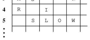
Figure 2: Example Solution 4 1 3 2 5 . . .
2
3
4
5 1
...
B
E
A
R
        T
        A
        I
        L
            I
    G
                N
    S
            O
               W
2
3
4
5 1
...
SLOW
AGAIN
BOY
TAIL
BEAR
Candidate Words
Input
The input data consist of one or more test cases each describing a puzzle trial. The first input line in each test case contains a positive integer N that represents the number of slots in the puzzle. This line is followed by N lines, each containing the row number and column number of a square where a slot begins, followed by the letter ‘A’ (if the slot is “Across”) or ‘D’ (if the slot is “Down”). The next N + 1 input lines contain candidate words that can be used in the puzzle solution.
The final test case is followed by a line containing the number zero.
Output
For each trial, print the trial number followed by the word that is not used in the puzzle solution, using the format in the example output. Observe the following rules: 1) Print a blank line after each trial. 2) If your uncle has made a mistake and the puzzle has no solution using the given words, print the word “Impossible”. For example, if Trial 2 has no solution, you should print “Trial 2: Impossible”. 3) If the puzzle can be solved in more than one way, print each word that can be omitted from a valid solution. The words can be printed in any order but each word must be printed only once. For example, if Trial 3 has a solution that omits the word DOG and two solutions that omit the word CAT, you should print “Trial 3: DOG CAT” or “Trial 3: CAT DOG”.
Sample Input
4
1   1   D
2   3   D
3   1   A
5   2   A
SLOW
AGAIN
BOY
TAIL
BEAR
0
Sample Output
Trial 1: BOYProblem D · Can’t Cut Down the Forest for the Trees Input: forest.in
Once upon a time, in a country far away, there was a king who owned a forest of valuable trees. One day, to deal with a cash flow problem, the king decided to cut down and sell some of his trees. He asked his wizard to find the largest number of trees that could be safely cut down.
All the king’s trees stood within a rectangular fence, to protect them from thieves and vandals. Cutting down the trees was difficult, since each tree needed room to fall without hitting and damaging other trees or the fence. Each tree could be trimmed of branches before it was cut. For simplicity, the wizard assumed that when each tree was cut down, it would occupy a rectangular space on the ground, as shown below. One of the sides of the rectangle is a diameter of the original base of the tree. The other dimension of the rectangle is equal to the height of the tree.
Many of the king’s trees were located near other trees (that being one of the tell-tale signs of a forest.) The wizard needed to find the maximum number of trees that could be cut down, one after another, in such a way that no fallen tree would touch any other tree or the fence. As soon as each tree falls, it is cut into pieces and carried away so it does not interfere with the next tree to be cut.
Input
The input consists of several test cases each describing a forest. The first line of each description contains five integers, xmin, ymin, xmax, ymax, and n. The first four numbers represent the minimal and maximal coordinates of the fence in the x- and y-directions (xmin < xmax, ymin < ymax). The fence is rectangular and its sides are parallel to the coordinate axes. The fifth number n represents the number of trees in the forest (1 ≤ n ≤ 100).
The next n lines describe the positions and dimensions of the n trees. Each line contains four integers, xi, yi, di, and hi, representing the position of the tree’s center (xi, yi), its base diameter di, and its height hi. No tree bases touch each other, and all the trees are entirely inside the fence, not touching the fence at all.
The input is terminated by a test case with xmin = ymin = xmax = ymax = n = 0. This test case should not be processed. Circular base: the original position of the tree height
Space occupied by tree after cutting
Output
For each test case, first print its number. Then print the maximum number of trees that can be cut down, one after another, such that no fallen tree touches any other tree or the fence. Follow the format in the sample output given below. Print a blank line after each test case.
Sample Input
0  0  10  10  3
3  3  2  10
5  5  3  1
2  8  3  9
0  0  0  0  0
Sample Output
Forest 1
2 tree(s) can be cut
Problem E · The Geoduck GUI Input: geoduck.in
Researchers at the Association for Computational Marinelife in Vancouver have been working for several years to harness various forms of aquatic life with the goal of constructing an underwater computer that can be seen from outer space. The current research focus is a breed of clam known as the geoduck (pronounced “GOOEY duck”), scientific name Panope abrupta. Geoducks can be as heavy as ten pounds and as long as 1 meter with their siphons or “necks” fully extended. Because of their life expectancy (up to 150 years), they seem to be good agents for manipulating a large-scale oceanic graphical user interface–hence, the “geoduck GUI” project.
Current research examines pairs of trained geoducks each starting in a distinct corner of a rectangular grid. They crawl across the grid spreading luminescent chemicals from containers attached to their shells. Geoducks are trained to move one grid unit horizontally or vertically per time unit to approximate a direction vector (each geoduck has a unique vector). If a move takes a geoduck off the edge of the grid, a trained dolphin immediately transports it to the cell on the opposite edge of the grid, effectively providing a “wraparound” mechanism. The entry point in the opposite edge cell is horizontally or vertically aligned with the exit point of the cell departed and the geoduck trajectory is maintained. Geoduck moves are synchronized; however, a geoduck halts when it enters a cell that it has previously visited. If two geoducks move into the same cell at the same time, they halt in that cell. If two geoducks attempt to move into each other’s cells at the same time, then they halt. A geoduck is initially placed at a grid corner so that its direction vector points “in” to the grid (e.g., if the x-component is positive and the y-component is negative, the starting position is at the minimum x-value and the maximum y-value in the grid).
Both geoducks begin at time t=1 in their respective (distinct) starting corners. A geoduck follows its vector as if the vector starting point were anchored to the center of geoduck’s initial cell position in the grid. It always moves to the next cell that is divided into regions by the vector (or its extension), with one exception. If the vector passes through a corner of the grid, the geoduck moves horizontally and then vertically to reach the next cell divided by the vector. Figure 1 shows several geoduck paths. The numbers in the cells indicate elapsed time. Grid cells are numbered from the lower left starting at zero in both the x and y directions. If the two geoducks in Figure 1 start at the same time in the same 6 by 5 grid, they each halt after 5 time units with a total of 10 cells illuminated.
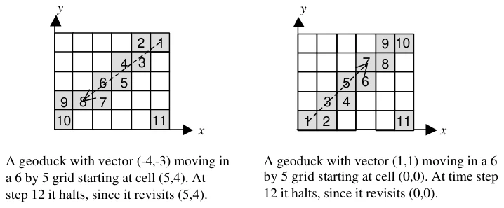
Figure 1: Sample geoduck paths
You must write a program to select pairs of geoducks that illuminate the maximum number of grid cells on the screen in the least amount of time. Repeat your calculations for various grid sizes and comb inations of geoducks.
Input
Input consists of a sequence of test cases each beginning with a line containing two integers m and n, 1 = m,n = 50, where m and n are not both 1. These are x and y dimensions of the grid. The second line of each test case contains an integer k, 2 = k = 10, representing the number of geoducks. At least one pair of geoducks will have distinct starting points. The next k lines each contain a pair of non-zero integers representing the x and y components of the k geoduck direction vectors.
The final test case is followed by two zeros.
Output
For each test case, print the test case number, the maximum number of illuminated cells, the minimum number of time units required to illuminate that number of cells, and the sequence numbers of each pair of geoducks that achieve these values. Print all pairs of geoducks that achieve maximum illumination in minimum time. The order of printing does not matter; however, do not print any pair twice for the same test case. Imitate the sample output shown below.
Sample Input
6 5
3
-4 –3
1 1
1 -1
0 0
Sample Output
Case 1   Cells Illuminated: 10   Minimum Time: 5
Geoduck IDs:  1  2
Geoduck IDs:  1  3
Problem F · A Major Problem Input File: major.in
In western music, the 12 notes used in musical notation are identified with the capital letters A through G, possibly followed by a sharp '#' or flat 'b' character, and are arranged cyclically as shown below. A slash is used to identify alternate notations of the same note.
C/B# C#/Db D D#/Eb E/Fb F/E# F#/Gb G G#/Ab A A#/Bb B/Cb C/B# …
Any two adjacent notes in the above list are known as a semitone. Any two notes that have exactly one note separating them in the above list are known as a tone. A major scale is composed of eight notes; it begins on one of the above notes and follows the progression tone-tone-semitone-tone-tone-tone-semitone. For example, the major scales starting on C and Db, respectively, are made up of the following notes:
C D E F G A B C Db Eb F Gb Ab Bb C Db
The following rules also apply to major scales:
- The scale will contain each letter from A to G once and only once, with the exception of the first letter of the scale, which is repeated as the last letter of the scale. 2. The scale may not contain a combination of both flat and sharp notes.
The note that begins a major scale is referred to as the key of the scale. For example, the scales above are the scales for the major keys of C and Db, respectively. Transposing notes from one scale to another is a simple matter of replacing a note in one scale with the note in the corresponding position of another scale. For example, the note F in the major key of C would transpose to the note Gb in the major key of Db since both notes occupy the same position in their respective scales.
You must write a program to transpose notes from one major scale to another.
Input
The input consists of multiple test cases, with one test case per line. Each line starts with a source key, followed by a target key, and then followed by a list of notes to be transposed from the major scale of the source key to the major scale of the target key. Each list is terminated by a single asterisk character. All notes on a line and the terminating asterisk are delimited by a single space.
The final line of the input contains only a single asterisk which is not to be processed as a test case .
Output
Each test case produces one or more lines of output. If the source and target keys are valid, then the first output line for each input line should read “Transposing from X to Y:” where X is the source key and Y is the target key. If either the source or target key is not valid a line which reads “Key of X/Y is not a valid major key”, where X/Y is the key that is not valid, should be output and the remainder of the input for that line skipped. If both the source and target key are not valid, report only the source key. For test cases that contain valid source and target keys, the first output line will be followed by one output line for each note to be transposed. If the note is a valid note in the major scale of the source key then the output line should read “M transposes to N” where M is the note in the source key and N is the corresponding note in the target key. If the input note is not a valid note in the major scale of the source key then the output line should read “M is not a valid note in the X major scale” where M is the input note and X is the source key. For either valid or non-valid notes, the output line should be indented in a consistent manner.
The output data for each input line should be delimited by a single blank line. The format of your output should be similar to the output shown below.
Sample Input
C Db F *
Db C Gb *
C B# A B *
C D A A# B Bb C *
A# Bb C *
*
Sample Output
Transposing from C to Db:
F transposes to Gb
Transposing from Db to C:
Gb transposes to F
Key of B# is not a valid major key
Transposing from C to D:
A transposes to B
A# is not a valid note in the C major scale
B transposes to C#
Bb is not a valid note in the C major scale
C transposes to D
Key of A# is not a valid major key
Problem G · Fixed Partition Memory Management Input file: memory.in
A technique used in early multiprogramming operating systems involved partitioning the available primary memory into a number of regions with each region having a fixed size, different regions potentially having different sizes. The sum of the sizes of all regions equals the size of the primary memory.
Given a set of programs, it was the task of the operating system to assign the programs to different memory regions, so that they could be executed concurrently. This was made difficult due to the fact that the execution time of a program might depend on the amount of memory available to it. Every program has a minimum space requirement, but if it is assigned to a larger memory region its execution time might increase or decrease.
In this program, you have to determine optimal assignments of programs to memory regions. Your program is given the sizes of the memory regions available for the execution of programs, and for each program a description of how its running time depends on the amount of memory available to it. Your program has to find the execution schedule of the programs that minimizes the average turnaround time for the programs. An execution schedule is an assignment of programs to memory regions and times, such that no two programs use the same memory region at the same time, and no program is assigned to a memory region of size less than its minimum memory requirement. The turnaround time of the program is the difference between the time when the program was submitted for execution (which is time zero for all programs in this problem), and the time that the program completes execution.
Input
The input data will contain multiple test cases. Each test case begins with a line containing a pair of integers m and n. The number m specifies the number of regions into which primary memory has been partitioned (1 ≤ m ≤ 10), and n specifies the number of programs to be executed (1 ≤ n ≤ 50).
The next line contains m positive integers giving the sizes of the m memory regions. Following this are n lines, describing the time-space tradeoffs for each of the n programs. Each line starts with a positive integer k (k ≤ 10), followed by k pairs of positive integers s1,t1,s2,t2,…,sk,tk, that satisfy si < si+1 for 1 ≤ i < k. The minimum space requirement of the program is s1, i.e. it cannot run in a partition of size less than this number. If the program runs in a memory partition of size s, where si ≤ s < si+1 for some i, then its execution time will be ti. Finally, if the programs runs in a memory partition of size sk or more, then its execution time will be tk.
A pair of zeroes will follow the input for the last test case.
You may assume that each program will execute in exactly the time specified for the given region size, regardless of the number of other programs in the system. No program will have a memory requirement larger than that of the largest memory region.
Output
For each test case, first display the case number (starting with 1 and increasing sequentially). Then print the minimum average turnaround time for the set of programs with two digits to the right of the decimal point. Follow this by the description of an execution schedule that achieves this average turnaround time. Display one line for each program, in the order they were given in the input, that identifies the program number, the region in which it was executed (numbered in the order given in the input), the time when the program started execution, and the time when the program completed execution. Follow the format shown in the sample output, and print a blank line after each test case. If there are multiple program orderings or assignments to memory regions that yield the same minimum average turnaround time, give one of the schedules with the minimum average turnaround time.
Sample Input
2 4
40 60
1 35 4
1 20 3
1 40 10
1 60 7
3 5
10 20 30
2 10 50 12 30
2 10 100 20 25
1 25 19
1 19 41
2 10 18 30 42
0 0
Sample Output
Case 1
Average turnaround time = 7.75
Program 1 runs in region 1 from 0 to 4
Program 2 runs in region 2 from 0 to 3
Program 3 runs in region 1 from 4 to 14
Program 4 runs in region 2 from 3 to 10
Case 2
Average turnaround time = 35.40
Program 1 runs in region 2 from 25 to 55
Program 2 runs in region 2 from 0 to 25
Program 3 runs in region 3 from 0 to 19
Program 4 runs in region 3 from 19 to 60
Program 5 runs in region 1 from 0 to 18
Problem H · Professor Monotonic’s Networks Input: sort.in
Professor Monotonic has been experimenting with comparison networks, each of which includes a number of two- input, two-output comparators. A comparator, as illustrated below, will compare the values on its inputs, i1 and i2, and place them on the outputs, o1 and o2, so that o1 ≤ o2 regardless of the relationship between the input values.
A comparison network has n inputs a1,a2,…,an and n outputs b1,b2,…,bn. Each of the two inputs to a comparator is either connected to one of the network’s n inputs or connected to the output of another comparator. Each of the two outputs from a comparator is either connected to one of the network’s n outputs or is connected to the input of another comparator. A graph of the interconnections of comparators must be acyclic. The illustration below shows a comparison network with four inputs, four outputs, and five comparators.
In operation, the network’s inputs are applied and the comparators perform their functions. Of course a comparator cannot operate until both of its inputs are available. Assuming a comparator requires one unit of time to operate, this sample network will require three units of time to produce its outputs. Comp -1 and Comp-2 operate in parallel, as do Comp-3 and Comp-4. Comp-5 cannot operate until Comp -3 and Comp-4 have completed their work.
Professor Monotonic needs help in determining which proposed comparison networks are also sorting networks, and how long they will take to perform their task. A sorting network is a comparison network for which the outputs are monotonically increasing regardless of the input values. The example above is a sorting network, since for all possible input values the output values will have the relation b1 ≤ b2 ≤ b3 ≤ b4.
Input
The professor will provide a description of each comparison network to be examined. Each description will begin with a line containing values for n (the number of inputs) and k (the number of comparators). These values satisfy 1 = n = 12 and 0 = k = 150. This is followed by zero or more non-empty lines, each containing at most 15 pairs of comparator inputs. The source of the input to each comparator is given by a pair of integers i and j. Each of these specifies either the subscript of a network input that is input to the comparator (that is, ai or aj), or the corresponding output of a preceding comparator.
The outputs of a comparator are numbered the same as its inputs (in other words, if the comparator’s inputs are i and j, the corresponding outputs are also labeled i and j). The order in which these pairs appear is significant, and affects the order in which the comparators operate. If two pairs contain an integer in common, the order of the a1
a2 b1
b2 Comp-1
Comp-2 a3
a4 b3
b4 Comp-3
Comp-4 Comp-5 i1
i2 o1
o2 corresponding comparators in the network is determined by the order of the pairs in the list. For example, consider the input data for the example shown:
4  5
1  2   3  4   1  3
2  4   2  3
This indicates there will be four input values and five comparators in the network. The first comparator (Comp -1) will receive its input values from network inputs a1 and a2. The second comp arator (Comp-2) will receive its input values from network inputs a3 and a4. The third comparator (Comp-3) will receive its first input from the first output of Comp-1, and will receive its second input from the first output of Comp -2. Similarly, the fourth comparator (Comp-4) will receive its first input from the second output of Comp -1, and will receive its second input from the second output of Comp -2. Finally, the fifth comparator (Comp-5) will receive its first input from the first output of Comp-4, and will receive its second input from the second output of Comp -3. The outputs b1,b2,…,bn are taken from the first output of Comp -3, the first output of Comp -5, the second output of Comp -5, and the second output of Comp-4, respectively.
A pair of zeros will follow the input data for the last network.
Output
For each input case, display the case number (cases are numbered sequentially starting with 1), an indication of whether the network is a sorting network or not, and the number of time units required for the network to operate (regardless of whether it is a sorting network or not).
Sample Input
4  5
1  2    3  4    1  3
2  4    2  3
8  0
3  3
1  2    2  3    1  2
0  0
Sample Output
Case 1 is a sorting network and operates in 3 time units.
Case 2 is not a sorting network and operates in 0 time units.
Case 3 is a sorting network and operates in 3 time units.
Problem I · A Vexing Problem Input: vexing.in
The game Vexed is a Tetris-like game created by James McCombe. The game consists of a board and blocks that are arranged in stacks. If the space to the immediate left or right of a block is open (that is, it contains no other block nor any part of the game board “wall”), then that block can be moved in that direction. Only blocks that are not part of the game board wall can be moved; “wall” blocks are stationary in all events. After a block is moved, if it or any other block no longer has anything under it, those blocks fall until they land on another block. After all blocks have landed, if any two or more identically-marked pieces are in contact horizontally and/or vertically, then those blocks are removed as a group. If multiple such groups result, then all groups are removed simultaneously. After all such groups are removed, all blocks again fall to resting positions (again, wall blocks do not move). This might then result in more groups being removed, more blocks falling, and so on, until a stable state is reached. The goal of the game is to remove all the movable blocks from the board.
Consider the simple example shown here. For reference purposes, number the rows of the board from top to bottom starting with an index value of zero, and number the columns from the left to right, also with a starting index value of zero. Board positions can be therefore be referenced as ordered (row, column) pairs. By additionally using an “L” or “R” to refer to a left or right push respectively, we can also use the ordered triple (row, column, direction) to indicate moves.
X X à X Y ß Y X Y Y X Y X Y X Y X Y
(A) (B) (C) (D)
X X à
X X à X X
(E) (F) (G) (H)
In (A) we have two choices for moves as shown in (B). These moves are (0,1,R) and (1,3,L) using the identification scheme defined above. Note that if we try (0,1,R), the resulting board state as shown in (C) is a dead end; no further moves are possible and blocks still remain on the board. If we choose the other move, however, the blocks at (1,2) and (2,2) are now in vertical contact, so they form a group that should be removed as shown by (D). The resulting board state is shown in (E), leaving the two moves shown by (F). Note that either move would eventually allow a solution, but (0,1,R) leads to a two move solution, whereas (2,1,R) leads to a three move solution. (G) and (H) show the final steps if we choose (0,1,R).
There are often many ways to solve a particular Vexed puzzle. For this problem, only solutions with a minimum number of moves are of interest. The minimum number of moves can sometimes be surprising. Consider another example. X
Y X
X Y
Z à Z X Z X
X X Z X X Z Y Z Z
Y Z X Y Z Z X Y X X X
X Z X Z X X
(A) (B) (C) (D)
In this example there are ten possible first moves, and there are in fact several ways to arrive at a solution. There is only one move in (A), however, that allows us to achieve a solution with the minimum number of moves. Observe the sequence of events shown if (3,1,R) is chosen as the first move.
Input
The input will consist of several puzzles. Each begins with a line containing integers giving the number of rows (NR) and columns (NC) in the puzzle, and a string of characters (terminated by the end of line) giving the name of the puzzle; these items are separated by one or more spaces. This line is followed by an NR by NC array of characters defining the puzzle itself; an end of line will follow the last character in each row. NR and NC will each be no larger than 9. The “outer walls” (in addition to “inner wall” blocks) on the left, right, and bottom will always be included as part of the puzzle input, and are represented as hash mark (#) characters. Moveable blocks are represented by capital letters which indicate the marking on the block. To avoid possible ambiguities, open spaces in the puzzle are represented in the input by a hyphen (–) rather than by spaces. Other than the outer walls, wall blocks and moveable blocks may be arranged in any stable pattern. Every input puzzle is guaranteed to have a solution requiring 11 or fewer moves.
A puzzle with zero dimensions marks the end of the input and should not be processed.
Output
For each input puzzle, display a minimum length solution formatted as shown in the sample output. In the event that there are multiple solutions of minimum length, display one of them.
Sample Input
4 5 SAMPLE-01
#A--#
##-B#
#AB##
#####
6 7 SAMPLE-02
#--Y--#
#-ZX-X#
#-##-##
#-XZ--#
####YZ#
#######
0 0 END
Sample Output
SAMPLE-01: Minimum solution length = 2
(B,1,3,L) (A,0,1,R)
SAMPLE-02: Minimum solution length = 9
(Y,0,3,R) (Z,4,5,L) (X,1,3,R) (Z,1,2,R)
(Z,1,3,R) (X,3,4,R) (X,3,2,R) (X,4,5,L)
(X,1,5,L)